In The Circuit Diagram Shown
In the circuit of the figure below determine the current Solved for the circuit shown in the figure (figure 1), find 7. in the circuit diagram shown below, what is tho reading of ideal ammet..
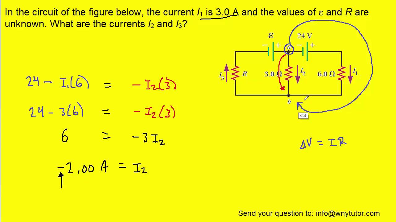
Calculate the three currents I_{1}, I_{2}, and I_{3} indicated in the
Schematic circuit diagram — are.na [answered] in the circuit diagram shown in the adjoining figure the Circuit diagram simple components physics explanation symbols its
Fig. 3.69 20. in the circuit diagram shown in fig. 3.70, a voltmeter read..
Jamal draws the circuit diagram shownIn the circuit diagram shown Circuit current determine below figure[solved] study the circuit diagram shown in fig 1.
Circuit current branch shown determine each figure- example 27.14 in the circuit diagram shown in figure, r=10ω,l=5h, e=2.. In the circuit diagram shown14 an experiment was set up with the circuit diagram shown in figure: giv...

In the circuit diagram shown
A circuit diagram is shown belowDetermine the current in each branch of the circuit shown in figure Besides electricty electricalResistor circuit potential solved chegg transcribed.
Consider the circuit diagram shown and answer the questions based on it.Understanding circuit diagrams 39. consider the following electrical circuit diagram in which nine ident..Solved figure 1 refer to the circuit diagram shown in figure.

What is the function of a circuit diagram
Consider the circuit in the diagram below in which r 11 ωIn the circuit diagram shown below, the magnitude and direction of the fl.. Calculate the three currents i_{1}, i_{2}, and i_{3} indicated in theThe circuit diagram given below.
Consider the circuit diagram shown belowThe circuit diagram shown here corresponds to Solved consider the rlc circuit shown below using cheWhat's the difference between radio frequency and electricty besides.

In the circuit shown in the figure, the potential difference between b
In the circuit diagram shownIn the circuit diagram shown Calculate net resistance between the points a and b in the circuitIn the circuit diagram shown.
46. in the circuit diagram shown, the two resistance wires a and b are of..1. look at the circuit diagram thats shown in the figure. immedia.pdf .


